

The simultaneous transmission of data and power to information technology end devices via balanced copper cabling is already widespread and continues to grow.
The international standardisation of Power over Ethernet (PoE) has played a key role in establishing the dual use of copper cabling for both data transmission and power delivery.
The advantages of this technology are clear. PoE enables the power supply to be controlled centrally and combined with data transmission services. This eliminates the need for an additional low-voltage power supply. While four-pair data cabling has traditionally been capable of supplying IT end devices with up to 72 W using 4PPoE, single-pair data cabling is now also becoming established for powering IT devices. Single Pair Power over Ethernet (SPoE) addresses the power requirements of the Internet of Things.
This brochure provides guidance on the design and planning of information technology cabling systems that use remote powering technologies such as PoE.
Advantages and Benefits
Power over Ethernet offers numerous advantages that provide tangible benefits for IT operators.

Savings in Material and Installation Costs for the 230 V
Power Supply, Including Cables and Sockets
Comprehensive Management and Monitoring Capabilities (SNMP)
Reduction in Energy Costs through Demand-Based Power Routing and
Deactivation of Unused Ports
Operating Principle
The operating principle of PoE is based on the transmission of electrical power between the power sourcing equipment (PSE) and the powered device (PD).
Power is supplied either via the unused data pairs or superimposed on the data signal via the pairs used for data transmission, known as phantom powering.
PSEs are divided into endspans and midspans. Endspans are Ethernet switches with integrated PoE functionality and are characterised by their compact design and straightforward management. Midspans are PoE injectors installed between the switch and the end device, enabling flexible, demand-based retrofitting.
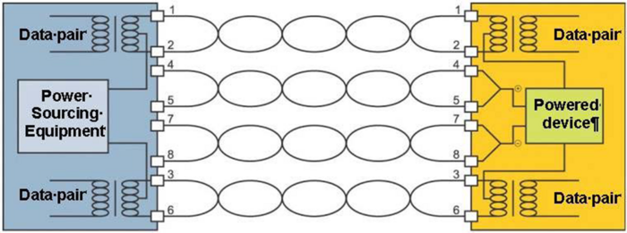
Schematic Diagram of PoE Transmission (Source: IEEE 802.3)
When an end device is connected, a start-up sequence detects whether it is PoE-capable, thereby protecting unsuitable devices.
The power sourcing equipment initially applies only a minimal current to the conductors, which under normal circumstances cannot damage the connected device. It then determines whether the powered device is PoE-compatible and only supplies the permitted power once compatibility has been confirmed.
Four-Pair Balanced Cabling
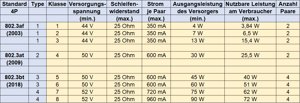
IEEE PoE Standards for Four-Pair Balanced Cabling
IEEE 802.3af, published in 2003, was the first PoE standard. It enabled IT devices to be supplied simultaneously with power and data via information technology cabling for the first time. Since then, the available power levels for IT devices have been continuously increased as the technology has evolved. IEEE 802.3bt, published in 2018, supports a usable power output of up to 72 W.
The technical model for PoE transmission is based on a maximum loop resistance of 25 ohms for the cabling channel. This value is derived from the specification for the maximum loop resistance of Class D, E, EA, F and FA cabling channels in accordance with ISO/IEC 11801 and EN 50173.
The maximum loop resistance of 25 ohms per 100 m approximately corresponds to an AWG 24/1 copper conductor with a diameter of 0.51 mm. The transmission distance can be increased by using copper conductors with a larger diameter.
Single-Pair Balanced Cabling
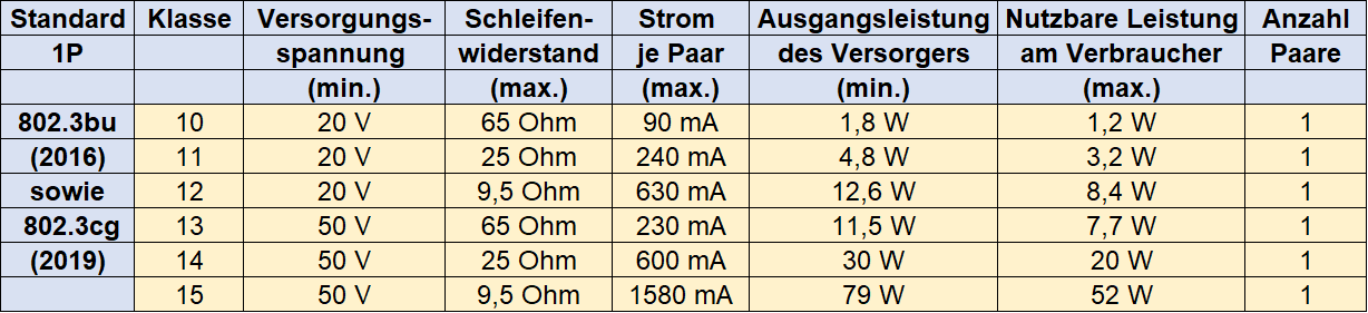
IEEE PoE Standards for Single-Pair Balanced Cabling
Like four-pair balanced cabling, Single Pair Ethernet (SPE) also supports the simultaneous transmission of data and power. In IEEE 802.3bu, published in 2016, this technology was still referred to as Power over Data Line (PoDL). IEEE has since adopted the more consistent term Single Pair Power over Ethernet (SPoE).
IEEE 802.3cg, published in 2019, specifies a Class 15 variant capable of supplying up to 52 W of usable power to the powered device, based on a maximum loop resistance of 9.5 ohms. This typically requires an AWG 18/1 copper conductor with a diameter of 1.02 mm.
There are numerous applications for Power over Ethernet.
Advancing digitalisation, combined with growing awareness of sustainability, is continuously creating new areas of application. The greatest potential is likely to be found in intelligent building management and smart lighting solutions.
IT Devices Typically Powered via PoE
VoIP Telephones
IP Cameras
WLAN Access Points
Bluetooth Devices
Motor and Drive Control
Access Control Systems
Call Systems
Digital Displays
Readers and Printers
Laptops
LED Lighting
Requirements for IT Cabling, Data Cables and Connectors
IT Cabling
Equipment used for the remote powering of devices via information technology cabling must comply with DIN IEC EN 62368-3, “Safety Aspects for DC Power Transfer through Communication Cables and Ports”.
The challenges associated with supplying power via information technology cabling include:
a) Global Effects
An increase in attenuation caused by the higher temperature of the installed cables. Unless this is compensated for by reducing the installed cable lengths, it may adversely affect the attenuation-to-crosstalk ratio of the transmission channel and consequently result in a higher system bit error rate.
b) Local Effects
Higher cable operating temperatures, particularly where the permitted operating temperature is exceeded
Damage to the contacts of the connecting hardware caused by mating or unmating connections while the supply current is flowing
In conjunction with EN TR 50174-99-1 and ISO/IEC TS 29125, EN 50174-2 and ISO/IEC 14763-2 provide guidance on the planning and assessment of cabling, cables and connecting hardware with regard to the thermal and electrical effects of remote powering.
Data Cables
Where a communication cabling system installed in accordance with the DIN EN 50173 or ISO/IEC 11801 series of standards is used to supply connected end devices remotely with power, for example via Power over Ethernet, the resulting increase in data cable temperature must be taken into account.
The temperature rise of data cables depends on the following factors:
Current load
Cable construction
Number of bundled cables
Installation conditions
As European and international data cable standards specify a maximum continuous operating temperature of 60 °C, a maximum ambient temperature of 50 °C has been agreed for power transmission via data cables. This allows for a maximum temperature rise of 10 °C.
Data cable temperature rise can be reduced:
By using data cables with a larger conductor cross-section, generally achieved by selecting higher cable categories. Category 7A data cables typically exhibit approximately 50% less temperature rise than Category 5 data cables.
By using shielded data cables. The metallic shield improves heat dissipation.
By reducing the number of cables within a bundle or installation trunking.
By improving air circulation within the installation environment.
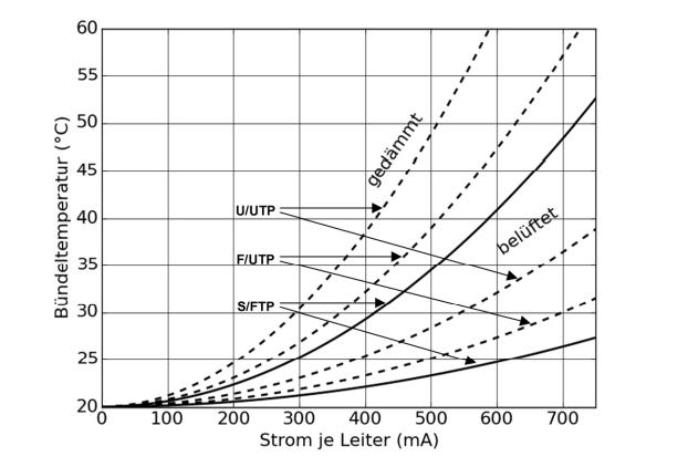
The following diagram shows the approximate temperature rise of commercially available data cables as a function of the current load. The calculation is based on a bundle of 37 data cables installed either in an environment with free air circulation or in an insulated installation environment.
At a current load of 500 mA per conductor, the selected S/FTP data cable exhibits a temperature rise of less than 5 °C in a ventilated installation and less than 15 °C in an insulated installation. By comparison, the U/UTP data cable exhibits a temperature rise of less than 10 °C in a ventilated installation and less than 30 °C in an insulated installation.
Connectors
Disconnecting a connector while it is carrying electrical load can produce arcs or sparks that damage the contacts. Frequent disconnection under load may result in contact erosion. This damage is irreversible and may ultimately cause the contacts to fail.
Port power management can help by switching off the voltage or power supply before connectors are disconnected or PoE end devices are removed from the network. However, intentional or accidental disconnection under load cannot be reliably prevented. Connector technology with separate contact and disconnection zones should therefore be used. Although this does not prevent wear within the disconnection zone, the operational contact area remains unaffected.
During qualification in accordance with IEC 60512-99-001 or IEC 60512-99-002, the connectors are subjected to a limited number of mating cycles under electrical load. The change in contact resistance must not exceed the specified limit.
ZVK Product Range and Recommendations
For IT cabling with remote power supply or Power over Ethernet, ZVK recommends the use of:
- copper data cables with a conductor cross-section of AWG 22/1 (0.64 mm), for example the EasyLan® Gold S/FTP Data Cable, AWG 22/1, Cat. 7A.
Data cables with a larger conductor cross-section have a lower DC resistance and lower attenuation. As a result, they exhibit lower temperature rise and power loss on the one hand, and lower voltage drop or a greater transmission distance on the other.
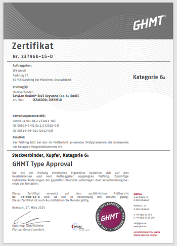
- connectors with staggered contact and separation zones, for example the EasyLan® fixLink® RJ45 Keystone Cat. 6A.
Upon request, ZVK provides advice on the planning and installation of IT cabling systems with PoE functionality.
ZVK determines the temperature rise of the data cables based on the cable construction, the number of cables within the bundle, the current load and the installation conditions.
In addition, the potential reduction in transmission channel length is calculated as a function of the cable construction or conductor cross-section and the resulting temperature rise.